Bit definition #
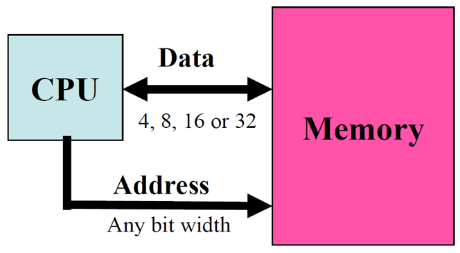
The number of bits describing the data path defines the MCU bit definition. As a general rule of thumb, the more bit definition, the more powerful, or fast, the MCU. “Old” microcontrollers are usually 8-bit. More recent microcontrollers are usually 32-bit. Note that the bit definition does not really limit the “functionalities” of the microcontroller, but rather its speed. Even with an 8-bit microcontroller, you can do floating point operation on 32-bit word, but it will take longer.
Common memory types in MCUs #
RAM #
Most microcontrollers have little amount of internal RAM (embedded in MCUs). For instance, the ATmega328P has only 2 Kbytes and this is a common amount, although some more powerfull microcontrollers can have more.
On a microcontroller, this small amount of RAM is typically used to only store variables (global, local, stack,…) and data of your program. The program code itself is stored in another type of memory, see below. However, use the small amount of RAM wisely and avoid declaring large static arrays of bytes.
EEPROM #
EEPROM stands for Electrically-Erasable-and-Programmable ROM. Internally, they are similar to EPROMs, but the erase operation is accomplished electrically, rather than by exposure to ultraviolet light. They usually have a higher cost and their write cycles are also significantly longer than RAM. EEPROM are typically used to store permanent data such as configuration parameters for an IoT device that can be obtained after the node has booted and that need to be restored/used when the node reboots.
Flash memory #
The flash memory is usually for storing the program itself. Note that in many cases, it is possible to store static strings that would be normally stored in RAM in the flash memory in order to avoid using the very limited amount of RAM. Typical amount of flash memory can be of several KB, from 32KB to 256KB or more for advanced microcontrollers. For instance, the ATmega328P has 32 Kbytes of flash memory to store the program.
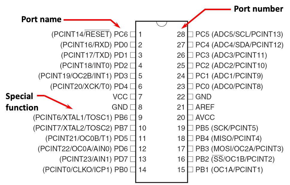
MCU ports/pins: the interface to the physical world #
A microcontroller has a number of ports or pins to interact with other electronic components. We will see later in the
Sensors section that those ports can be connected to physical sensors in order to interact with the physical world, which is one of the unique features of IoT.
A pin can be at LOW level (usually 0V), HIGH level (5V or 3.3V depending on the operating voltage of the board) or something in between.
Pins can be either INPUT, when you want to take information into the MCU, or OUTPUT when you want to change the state of something outside the MCU (turn a led/motor ON or OFF, etc.). For instance, you can power a low-power physical sensor with a pin configured as OUTPUT, and set the pin to HIGH. Usually, pins default to input direction on power-up or reset. Your program can set or change the directionality of a pin at any time.
Some pins are called analog pins because they have an embedded analog-to-digital converter in which case you will be able to read a digital value from the analog pin to convert that digital value into the original voltage applied to that pin. This is usually how a program can get data from an analog sensor.
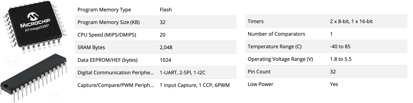
Example: the ATmega328p #
The Atmel 8-bit AVR RISC-based microcontroller combines 32 KB ISP flash memory with read-while-write capabilities, 1 KB EEPROM, 2 KB SRAM, 23 general-purpose I/O lines, 32 general-purpose working registers, 3 flexible timer/counters with compare modes, internal and external interrupts, serial programmable USART, a byte-oriented 2-wire serial interface, SPI serial port, 6-channel 10-bit A/D converter (8 channels in TQFP and QFN/MLF packages), programmable watchdog timer with internal oscillator, and 5 software-selectable power-saving modes. The device operates between 1.8 and 5.5 volts. The device achieves throughput approaching 1 MIPS/MHz.
Quoted from wikipedia
From microcontroller to microcontroller board #
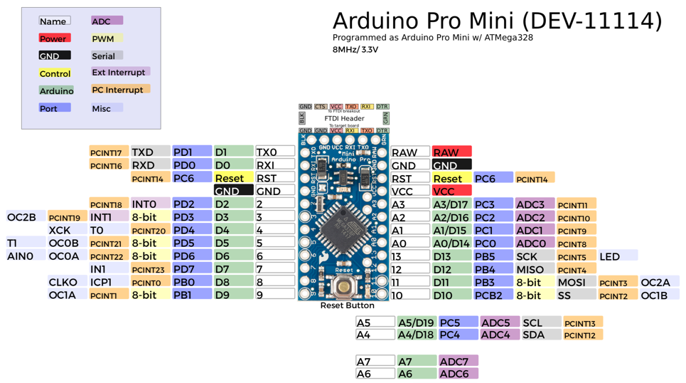
Arduino boards with ATmega328p #
The ATmega328p microcontroller is used in the Arduino Uno, Arduino Nano and Arduino Pro Mini boards.
Pin schematic of the Arduino Pro Mini #
The growing ecosystem #
Since the revolution created by the first iconic Arduino boards the microcontroller ecosystem is growing at a fast rate! There are now plenty of nice boards from many manufacturers, with a wide range of functionalities, from very low-power to very powerful to boards, even embedding micro Python programming environment, there are a board for every usage!
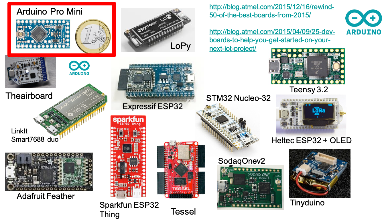
See for instance this article presenting 10 Boards to Start IoT Development in 2021.
Enjoy!
2021 - Congduc Pham