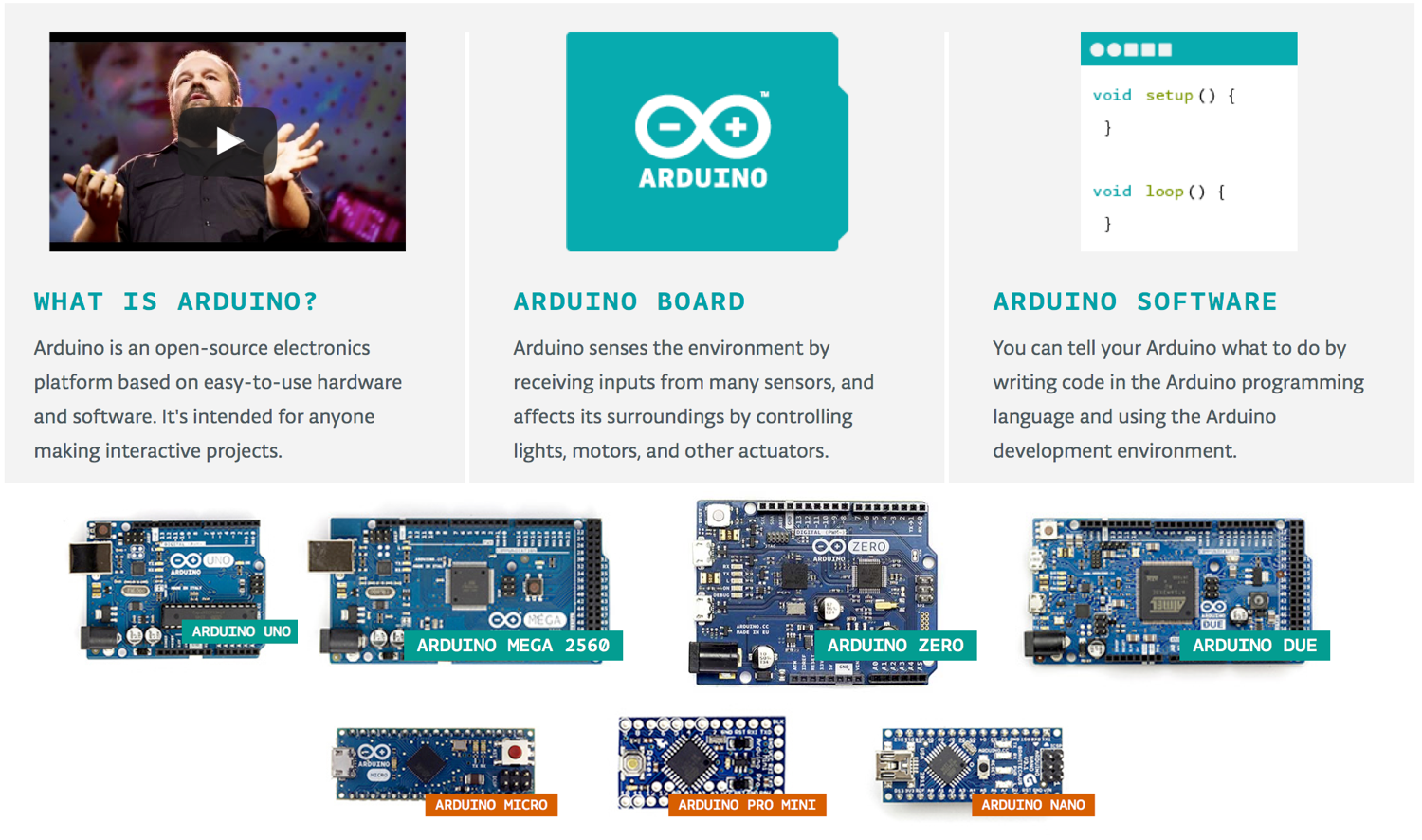
What is Arduino? #
Arduino is an open-source platform designed for artists, designers, hobbyists, hackers and anyone interested in creating interactive objects or environments. It consists of a circuit board, which can be programmed (referred to as a microcontroller board, see
Microcontoller section) and a software called Arduino IDE (Integrated Development Environment), which is used to write the computer code and upload this code to the physical board.
An Arduino board can interact with buttons, LEDs, motors, speakers, GPS units, cameras, the internet, and even your smartphone or your TV! This flexibility combined with the fact that the Arduino software is free, the hardware boards are pretty cheap, and both the software and hardware are easy to learn has led to a large community of users who have contributed to produce library code and released instructions for a huge variety of Arduino-based projects.
The key features of Arduino are listed below:
-
Arduino boards read signals from different sensors through analog or digital pins and can turn those signals into an output such as turning LED on/off, activating a machine, connecting to the clouds and many other actions.
-
You can control your board functions by sending a set of instructions to the microcontroller on the board via Arduino IDE (referred to as uploading software).
-
Unlike most previous programmable circuit boards, most of Arduino does not need an extra piece of hardware (called a programmer) in order to load a new code onto the board. You can simply use a USB cable.
-
Additionally, the Arduino IDE uses a simplified version of C++, making it easier to learn to program.
-
Arduino provides a standard form factor that breaks the functions of the micro-controller into a more accessible package.
The main components of the Arduino ecosystem is illustrated below with the main Arduino boards that made the whole Arduino concept successful.
Video on Arduino Course for Beginners #
You may want to start by watching this great video on Arduino Course for Beginners from freeCodeCamp.org. It is quite a complete, and long course, so you may watch the introduction and come back later directly to specific sections of the video that are listed in the video description part.
Start using this online tutorial #
In this online tutorial we illustrate examples with the Arduino UNO Rev3 version as the hardware platform but other Arduino boards can be used such as the Arduino Nano or the Arduino ProMini.
You can download all examples of this tutorial
here. The .zip archive also contains all the required libraries for the examples. Unzip the archive to get a sketch folder that will be used later on with the Arduino programming environment.
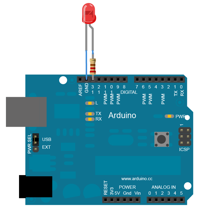
Blink example #
The Blink example shows the simplest thing you can do with an Arduino to see physical output: it blinks the on-board LED or a LED with 220 ohm resistor (see Figure). A LED usually has a longer pin (anode) which should be connected to the + side. It is on this pin that one should place a resistor to be connected to the Arduino pin to power (thus controlling) the LED. If the pin length is not obvious, note the particular shape of the anode compared to the shape of the cathode (to be connected to ground, i.e. - side). This program turns the LED on for one second, then off for one second, repeatedly.
There are mainly 2 functions: setup() and loop(). setup() is called once mainly for initialization purposes and loop() will loop forever and mainly codes for the behavior of the device. There are then specific functions and keywords for Arduino boards to read from various input pin and eventually act back on the system by writing to some output pin. More details will be given in the
Introduction to Arduino IDE section.
Blink code #
/********************
 * Program: Blink
 * Description: Turns on an LED on for one second, then off for one second, repeatedly.
 * This example code is in the public domain.
 ********************/

// Pin 13 has an LED connected on most Arduino boards.
int led = 13;

// the setup routine runs once when you press reset:
void setup() {
  // initialize the digital pin as an output.
  pinMode(led, OUTPUT);
}

// the loop routine runs over and over again forever:
void loop() {
  digitalWrite(led, HIGH);   // turn the LED on (HIGH is the voltage level)
  delay(1000);               // wait for a second
  digitalWrite(led, LOW);    // turn the LED off by making the voltage LOW
  delay(1000);               // wait for a second
}
Using breadboard #
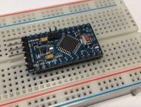
It is common, and practical when experimenting and prototyping, to use a breadboard to connect the various components. Small form factor Arduino board such as Arduino Nano or Arduino ProMini can be directly plugged on the breadboard, but for large form factor boards, such as the Arduino Uno, the breadboard is used to easily connect sensors or various modules.
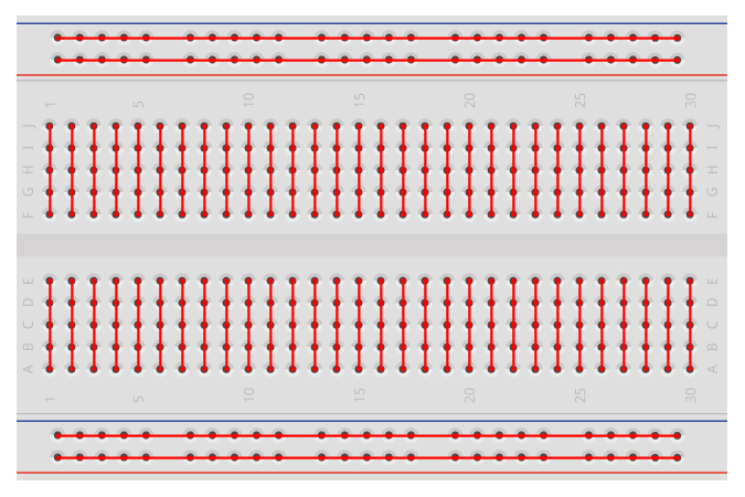
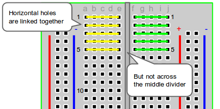
A breadboard works as follows. Horizontal lines are linked together, but not across the middle divider. Vertical lines are usually for VCC and GND lines, and are continuously linked. On most breadboards, you have therefore 2 VCC/GND pairs, one on each side of the breadboard.
It is a good practice to connect the power and ground line of the breadboard with the corresponding pin of the Arduino board so that all sensors can easily be connected to those lines.
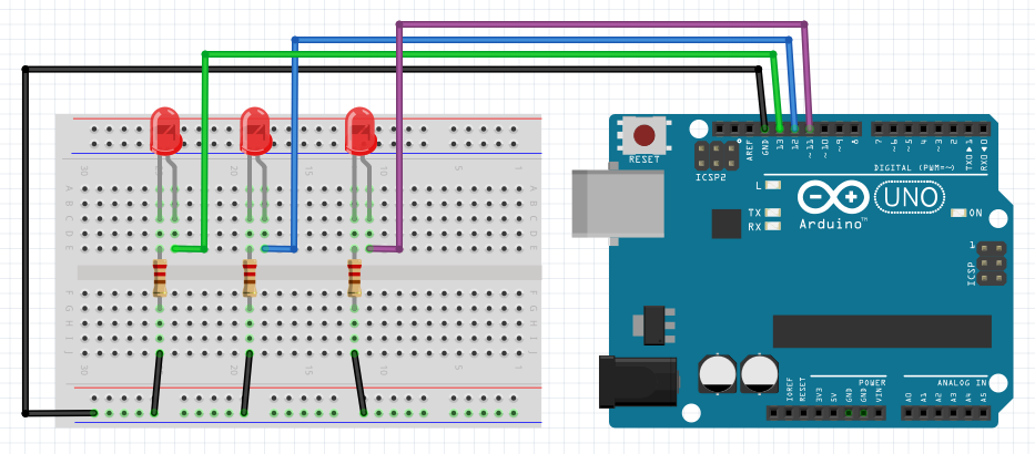
The previous example with a led can be made on a breadboard and easily extended as power and ground line are ealisily available on the breadboard. Here, in the led example, each led’s power pin is controlled separately and this is why they are directly connected to a digital pin of the Arduino board.
Enjoy!
2018 - Muhammad Ehsan, Mamour Diop & Congduc Pham