Overview #
Arduino_LoRa_Demo_Sensor is a very simple demo sketch for training purpose. The main program, i.e.
Arduino_LoRa_Demo_Sensor.ino can be left unchanged by the students. They just have to
add/modify code in
my_demo_sensor_code.h and
my_demo_sensor_code.cpp to adapt the code for a given physical sensor. The provided example reads from either an LM35DZ or a TMP36 analog temperature sensor.
Arduino board with LoRa radio module #
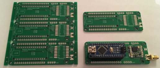
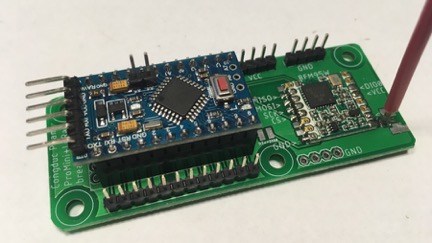
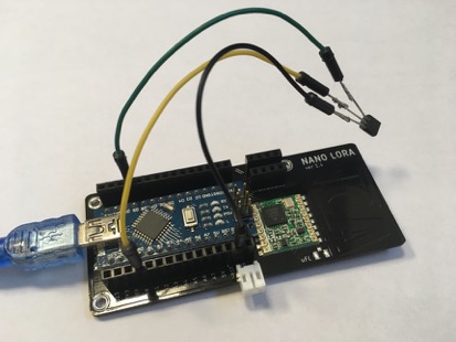
We mainly use either an Arduino Nano (5V, 16MHz) or an Arduino ProMini (3.3v, 8MHz) mounted on a simple PCB which hosts the RFM95 LoRa radio module. The advantage of the Arduino Nano is to avoid the external USB-Serial interface. The PCBs is freely available (Gerber files for the PCB manufacturer) from our GitHub at https://github.com/CongducPham/LowCostLoRaGw#pcbs. You can also find on this GitHub Gerber files of other LoRa components to build a whole device-gateway LoRa solution.
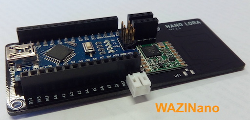
If you have the simple WaziNano board that has been integrated within the EU H2020 WAZIUP & WAZIHUB projects you can also use it. It has an integrated 868MHz antenna which is realized in collaboration with Pr. F. Ferrero from University of Nice.
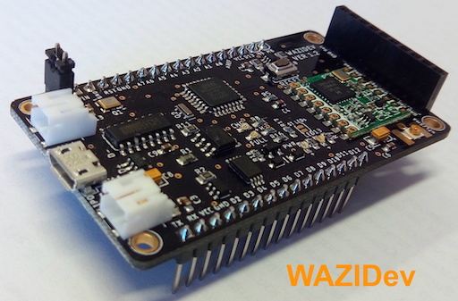
There is also the WaziDev board developed by WAZIUP e.V. that specifically targets integration purpose as the microcontroller is directly integrated into the board. Additionally, the WaziDev has many interesting features compared to other available boards on the market: integrated MOSFET for high power modules (such as GPS), possibility of activate or deactivate various LEDs for energy optimization purposes,…
Code example #
For better understanding, we will define some important basic parameters for the LoRa sensor to start with.
In the demo sensor header file #
my_demo_sensor_code.h. We define the PIN to read the value from the sensor. For this example, we will use PIN A0 to read the
output of the sensor.
#define PIN_READ A0
then we define the pin to power up the board. For this example, we selected pin 9. You can also connect the sensor directly to a VCC pin for this simple example but then you will not be able to power down the connected sensor.
#define PIN_POWER 9
also chose appropriate voltage scale for the board, 3300.0 for 3.3V and 5000.0 for 5V. The Arduino Nano is a 5V board. For the ProMini, we advise the 3.3V version but if you have the 5V version, set the voltage scale to 5000.0. The WaziDev board is a 3.3V board. If you are using a digital sensor you probably don’t need the scaling factor.
#define VOLTAGE_SCALE 3300.0
In the demo sensor code file #
my_demo_sensor_code.cpp. We start with defining the nomenclature string. Here, you can use a maximum of 3 characters. If you need more characters, just increase the size of the char array (be careful, the number of available characters is the size of the char array minus 1). But we recommend to not go beyond 5 characters because these characters will be sent wirelessly so more characters means longer packets. Here “TC” is a short way to refer to temperature in celcius. If you use a photoresistor, you can change the nomenclature string to “LUM” for instance. Note that this nomenclature is a completely user-defined string that will be used in the cloud platform to better identified the sensed value.
char nomenclature_str[4]="TC";
We defined function sensor_Init() for initialization of the input and output pin for the temperature sensor.
void sensor_Init() {
  pinMode(PIN_READ, INPUT);
  pinMode(PIN_POWER, OUTPUT);
}
In function sensor_getValue(), we define the way we read a value from the temperature sensor. In this example, we are using LM35DZ simple analog temperature sensor. You should verify the equation to calculate the sensed value for the sensor you are using. If you want to use one of the sensors you saw in previous examples (for instance the photoresistor or the DHT22), you have to use appropriate copy/paste to adapt the code to the sensor you are using.
double sensor_getValue() {

  //power up the sensor
  digitalWrite(PIN_POWER, HIGH );
  //wait a bit
  delay(500);

  //read the raw sensor value
  int value = analogRead(PIN_READ);

  //power down the sensor
  digitalWrite(PIN_POWER, LOW);
  Serial.print(F("Reading "));
  Serial.println(value);

  double sensor_value;
  //change here how the temperature should be computed depending on your sensor type
  sensor_value = (value*VOLTAGE_SCALE/1024.0)/10;

  return sensor_value;
}
Here is the WaziNano board with the analog LM35DZ temperature sensor that will be used.
In the main program #
The LoRa communication library to drive the LoRa radio module is referred to as the SX12XX library. It is originally written by Sturt Robinson and can support several LoRa chips versions: SX1261/62/68, SX1272/76/77/78/79 and SX1280/81. We modified it for our own purposes and added advanced functionalities. You will need to copy the library into your sketch/libraries folder. Our modified SX12XX library can be downloaded from our github repository: github:https://github.com/CongducPham/LowCostLoRaGw/tree/master/Arduino/libraries/SX12XX/src.
The SX12XX library is already included in the .zip archive that contains all the examples of this online tutorial with all the required libraries. If you haven’t done it yet, you can download the .zip archive here. Unzip the archive to get a sketch folder that will be used later on with the Arduino programming environment.
Defining the radio type #
The sketch starts by defining which LoRa chip family we are using. Here we used the HopeRF RFM95W radio module which is based on the SX1276 so we uncomment only the corresponding #define statement.
//#define SX126X
#define SX127X
//#define SX128X
When defining the correct LoRa chip model, the example template will include the corresponding header file: SX126X_RadioSettings.h or SX127X_RadioSettings.h or SX128X_RadioSettings.h. Each header file will define some LoRa parameters needed to run the LoRa rado module.
You do not need to worry much about most of the parameters and you can just for the moment leave them as they are defined by default. We are however going to describe some of the parameters to better understand the configuration of the LoRa transmission.
Radio setting file #
First, there are 2 important parameters that define the LoRa BW and SF parameters (see the LoRa radio section.
const uint8_t Bandwidth = LORA_BW_125;
const uint8_t SpreadingFactor = LORA_SF12;
Second, it is necessary to indicate in which frequency band you will be transmitting. Here we are using the 868MHz band. Note that the frequency band mostly depends on regulations defined for each country or region. For a given frequency band, it may be necessary to have a different LoRa chip. For instance SX1272/76 support well the 868MHz and 900MHz frequency band. If you want to use the 433MHz frequency band you may need to use a radio module based on the SX1278/79 to have better performances. For now, let’s just use to 868MHz band with the RFM95W which is based on the SX1276.
#define BAND868
//#define BAND900
//#define BAND433
For each frequency band, several frequencies/channels will be defined and a default frequency will be used. For 868MHz band, we have 15 channels, from CH_04_868 to CH_18_868, and the default frequency is set to CH_10_868 which value is 865.2MHz.
const uint32_t DEFAULT_CHANNEL=CH_10_868;
LoRa transmission #
You can change the LoRa node address here. It is important if you are working in several groups that each physical device has a different address. So coordinate with the other students to use a different address for each device. The address is a numeric value between 2 and 255 as address 1 is reserved for the gateway.
uint8_t node_addr=9;
In the setup() function, we set up and initialize all the required parameters. Initialisation of depends on the LoRa chip so there are codes dedicated to either SX126X, SX127X or SX128X. You normally do not have to change anything in the setup() function. Note the call to sensor_init() function to run the physical sensor specific initialisation.
sensor_Init();
Then we move on to the loop() function, which is supposed to run in a loop forever. First we call the function sensor_getValue() which we defined in my_demo_sensor_code.cpp to get the sensed value.
sensor_value = sensor_getValue();
Here we write the message that will be sent. We use the following format \!TC/22.5 for instance. The \! prefix will trigger at the gateway the upload of the received data to remote clouds. Remember that nomenclature_str is defined previously in my_demo_sensor_code.h as “TC”.
uint8_t r_size;
  char float_str[10];

  //the recommended format  \!TC/22.5
  //convert the floating value into a string
  ftoa(float_str,sensor_value,2);
  r_size=sprintf((char *)message, "\\!%s/%d" , nomenclature_str, (int)sensor_value);
Then we check for a free radio medium prior to transmitting the packet.
LT.CarrierSense();
The transmission of the packet is realized with the LT.transmitAddressed() function that takes 8 parameters: the buffer message to be sent, the number of bytes to be sent, the packet type (here it is PKT_TYPE_DATA), the destination address (here it is DEFAULT_DEST_ADDR which is defined as 1 for the gateway), the source address, a timeout value (here it is set to 10000ms), the transmission power in dBm (here MAX_DBM is defined as 14dBm in SX127X_RadioSettings.h) and finally WAIT_TX which indicates that we will wait for the transmission to finish before we return from the LT.transmitAddressed() function.
LT.transmitAddressed(message, r_size, PKT_TYPE_DATA, DEFAULT_DEST_ADDR, LT.readDevAddr(), 10000, MAX_DBM, WAIT_TX)
The function return 0 if there is an error. It returns the number of bytes transmitted otherwise.
After transmission, we remain idle for 1 minute.
nextTransmissionTime=millis()+60000;
If you open the Arduino IDE’s Serial Monitor window, you should see something similar to the following output:
Simple LoRa sensor demo
Arduino Pro Mini detected
ATmega328P detected
LoRa Device found

SX1276,865200000hz,SF12,BW125000,CR4:5,LDRO_On,SyncWord_0x1424,IQNormal,Preamble_8
SX1276,PacketMode_LoRa,Explicit,LNAgain_Boosted

Setting Power: 14
node addr: 9
SX127X successfully configured
Reading 323
Sensor value is 20.50
Sending \!TC/20.50
Real payload size is 10
\!TC/20.50
--> CS1
--> CAD 160
OK1
CRC,A808
LoRa pkt size 10
LoRa pkt seq 0
LoRa Sent in 1317
The SX12XX communication library #
You can have a look at the original SX12XX communication library github repository, especially at the section on library functions.
Next step: IoT gateway and IoT clouds #
Click here
Enjoy!
2019 - Muhammad Ehsan, Mamour Diop & Congduc Pham