last
update: June 19th, 2012.
Understanding the Castalia (v3.2) framework
------------------------------------------------------------
Author: Congduc
Pham, LIUPPA labs, University of Pau, France
------------------------------------------------------------
See
Congduc's page on wireless sensor networks research
This document provides additional information to those found on the
Castalia web site or in the Castalia user's manual that may be useful
for those who wants to quickly understand how Castalia is architectured
and how new behaviors could be introduced.
1. Introduction
The official web site of Castalia is http://castalia.npc.nicta.com.au/.
Here is a list of chronological material/things you should read/do in
order to
get used to Castalia and begin working with it.
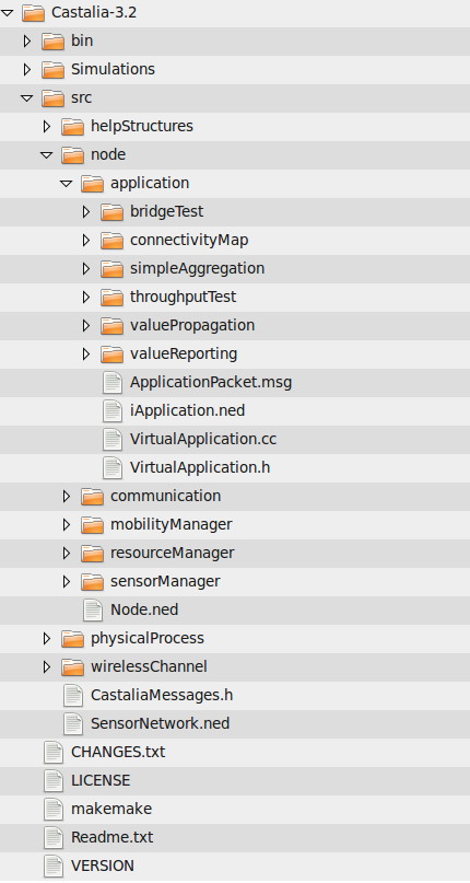
4. Understanding the structure of Castalia
Castalia uses the OMNET++ features to define the architecture of a
sensor node. All definitions are described and implemented in the
Castalia-3.2/src
directory. Here is a snapshoot of the Castalia forder
hierarchy.
The Node module
is the main component: it includes most of the other
modules such as the routing or radio module (in the
src/node/communication
folder), and of course the application modules
(in the src/node/application
folder). Regarding the application module,
you must understand that the behavior of a sensor node depends on which
application module you specify in the omnetpp.ini
file with the
SN.node[*].ApplicationName
= "ValuePropagation" line.
Actually, when you build the Castalia binary, all the object files are
included, even those that defines the other Castalia application
examples (valuePropagation,
connectivityMap,...). However, with the
definitions in the omnetpp.ini
file the correct application module is
applied at runtime for each sensor node. For instance, this is what can
be found in the Simulations/valuePropagation/omnetpp.ini
file)
#
----------------------------------------------------------------
# Define the
application module you want to use and its parameters
#
----------------------------------------------------------------
SN.node[*].ApplicationName
= "valuePropagation"
In this way, all nodes will have the behavior of the valuePropagation
implementation, which is defined in the
src/node/application/valuePropagation
folder where you will find .cc
and .h files.
Note that this is an efficient way to separate the implementation of
the application part of the sensor node (that is mainly user specific)
from the other parts such as routing, energy management,...
If you look at the
src/node/application/valuePropagation/ValuePropagation.cc
file you will find a line indicating:
Define_Module(ValuePropagation);
which makes the link between the behavior that is implemented and the
name of the module you have to put in the SN.node[*].ApplicationName
field.
At this stage, if you look at the src/node/Node.ned
file that defines
the logical structure of a sensor node, we will find the following
information:
package node;
import node.mobilityManager;
// The sensor node module. Connects to the wireless channel in order to
communicate
// with other nodes. Connects to psysical processes so it can sample
them.
module Node {
parameters:
//node location is defined by five parameters
below
double xCoor = default (0);
double yCoor = default (0);
double zCoor = default (0);
double phi = default (0);
double theta = default (0);
double startupOffset = default
(0);
//node startup offset (i.e. delay), in seconds
double startupRandomization = default
(0.05);
//node startup randomisation, in seconds
// Node will become active startupOffset +
random(startupRandomization)
// seconds after the start of simulation
string ApplicationName;
//the name of
the implemented Application Module
string MobilityManagerName = default
("NoMobilityManager"); //the name of the implemented
Mobility Module
gates:
output toWirelessChannel;
output toPhysicalProcess[];
input fromWirelessChannel;
input fromPhysicalProcess[];
submodules:
MobilityManager: <MobilityManagerName> like
node.mobilityManager.iMobilityManager;
ResourceManager:
node.resourceManager.ResourceManager;
SensorManager: node.sensorManager.SensorManager {
gates:
fromNodeContainerModule[sizeof(toPhysicalProcess)];
toNodeContainerModule[sizeof(toPhysicalProcess)];
}
Communication:
node.communication.CommunicationModule;
Application: <ApplicationName> like
node.application.iApplication;
connections:
Communication.toNodeContainerModule -->
toWirelessChannel;
fromWirelessChannel -->
Communication.fromNodeContainerModule;
Application.toCommunicationModule -->
Communication.fromApplicationModule;
Application.toSensorDeviceManager -->
SensorManager.fromApplicationModule;
Communication.toApplicationModule -->
Application.fromCommunicationModule;
SensorManager.toApplicationModule -->
Application.fromSensorDeviceManager;
for i = 0..sizeof(toPhysicalProcess) - 1 {
fromPhysicalProcess[i] -->
SensorManager.fromNodeContainerModule[i];
SensorManager.toNodeContainerModule[i] --> toPhysicalProcess[i];
}
ResourceManager.toSensorDevManager -->
SensorManager.fromResourceManager;
ResourceManager.toApplication -->
Application.fromResourceManager;
ResourceManager.toNetwork -->
Communication.fromResourceManager2Net;
ResourceManager.toMac -->
Communication.fromResourceManager2Mac;
ResourceManager.toRadio -->
Communication.fromResourceManager2Radio;
}
If you look at the submodules section, you can easily understand that a
sensor node is composed of a mobility module, a resource module, a
device manager module, a network module and an application module,
which implements what the sensor is doing. It is quite
interesting to see the CommunicationModule
defined in the src/node/nommunication/CommunicationModule.ned
file to further understand the hierarchical design of Castalia:
package
node.communication;
module CommunicationModule {
parameters:
string MACProtocolName = default ("BypassMAC");
string RoutingProtocolName = default
("BypassRouting");
gates:
output toApplicationModule;
output toNodeContainerModule;
input fromApplicationModule;
input fromNodeContainerModule;
input fromResourceManager2Net;
input fromResourceManager2Mac;
input fromResourceManager2Radio;
submodules:
Radio: node.communication.radio.Radio;
MAC: <MACProtocolName> like
node.communication.mac.iMac;
Routing: <RoutingProtocolName> like
node.communication.routing.iRouting;
connections:
fromApplicationModule -->
Routing.fromCommunicationModule;
Routing.toCommunicationModule -->
toApplicationModule;
Routing.toMacModule --> MAC.fromNetworkModule;
MAC.toNetworkModule --> Routing.fromMacModule;
MAC.toRadioModule --> Radio.fromMacModule;
Radio.toMacModule --> MAC.fromRadioModule;
fromNodeContainerModule -->
Radio.fromCommunicationModule;
Radio.toCommunicationModule -->
toNodeContainerModule;
fromResourceManager2Net -->
Routing.fromCommModuleResourceMgr;
fromResourceManager2Mac -->
MAC.fromCommModuleResourceMgr;
fromResourceManager2Radio -->
Radio.fromCommModuleResourceMgr;
}
So basically, you may understand now that if you want to start using
Castalia with the various application modules that is shipped with the
Castalia distribution you just have to define an omnetpp.ini
file that
changes the SN.node[*].ApplicationName
field according to what behavior you want to use (possibly a
behavior that you personnaly wrote). This is basically what is done in
the Simulations
folder where you will find various subfolders
corresponding to the application module used: simpleAggregation,
valuePropagation, valueReporting,... In each of these folders
you will
find the same elements: an omnetpp.ini
file that defines the variables
for the simulation and a shell script file that launches the
bin/CastaliaBin
executable that will parse the omnetpp.ini
file to know
will modules have to be called at runtime. One of these modules is of
course the application module. Most of all these omnetpp.ini
files have
similar sections that defines what module to use. Here is a portion of
the
Simulations/valuePropagation/omnetpp.ini
file:
[General]
# ==============================================
# Always include the main Castalia.ini file
# ==============================================
include ../Parameters/Castalia.ini
sim-time-limit = 10s
SN.field_x = 60 # meters
SN.field_y = 60 # meters
SN.numNodes = 16
SN.deployment = "4x4"
include ../Parameters/PhysicalProcess/node0_asssignedValue40.ini
SN.node[*].Communication.Radio.RadioParametersFile =
"../Parameters/Radio/CC2420.txt"
SN.node[*].Communication.MACProtocolName = "TunableMAC"
SN.node[*].ApplicationName = "ValuePropagation"
SN.node[*].Communication.MAC.listenInterval = 10
SN.node[*].Communication.MAC.dutyCycle = 0.1
SN.node[*].Communication.MAC.beaconIntervalFraction = 1.0
SN.node[*].Communication.Radio.TxOutputPower = "0dBm"
You can also see that choosing a specific behavior for the wireless
channel,
or the MAC layer, or the routing protocol is simply done by including
the appropriate .ini file. In this example we have the following
settings:
- the radio hardware is the Telos CC2420 that is found in most of
the sensor hardware
- the MAC layer is the tunable MAC which accepts many parameter
changes
- there is no routing since it use the default "bypass" module
- the application behavior the the valuePropagation
implementation
You can know the list of the various alternative behaviors by looking
into the
Simulations/Parameters
folder.
5. Understanding some Castalia communication model parameters, see
section 4 of the Castalia User's
Manual
6. Adding you own application behavior, see section 5 of the
Castalia User's Manual
7. Adding your own network protocols
Castalia has been developped for being easily extended. In this section
we will focus specifically on how to add new network behavior (routing,
MAC, ...). These new protocols will most likely be part of the Node
module so src/node
is certainly the dedicated folder for adding your new code. First of
all, you have to include your code in the development tree so that
compiling Castalia will include your own code. It is very similar in
adding a new application module.
Suppose that you want to implement a new MAC behavior called CL-MAC (see
B. Kechar et al.) .
Here are the main steps:
- go into src/node/communication/mac
directory and create a new folder called clMac.
You can use an existing MAC implementation to have a starting point
for implementing you new Mac protocol since many things may be similar.
For instance, you can copy all the file in the
src/node/communication/mac/tunableMac folder into you new clMac
folder. You can then use sed to
change every occurence of "TunableMAC"
by "CLMAC"
in both .cc and .h files
> cd
clMac
> cat TunableMAC.ned | sed -e
's/TunableMAC/CLMAC/g' > CLMac.ned
> cat TunableMAC.cc | sed -e
's/TunableMAC/CLMAC/g'
> CLMac.cc
> cat TunableMAC.h | sed -e
's/TunableMAC/CLMAC/g' > CLMac.h
go into the Castalia root directory
>
./makemake
> make
- Don't forget to add or remove in the CLMac.ned
file
any variables
that you want to introduce/remove in your CLMac
module
- After implementing the behavior of you own MAC layer, you can set
in the omnetpp.ini
file (the one in Simulations/valuePropagation
for instance) that the MAC layer of sensor nodes now uses your
own implementation with the following lines:
SN.node[*].Communication.MACProtocolName
= "CLMAC"
You can test all these steps and try to compile Castalia again even if
you are not changing the implementation of your CLMac.
If you based CLMAC
on TunableMAC,
Castalia should compile and allows you to incrementally change CLMac.
Note that you could test if the introduction of CLMac
is successful by defining for the valuePropagation
application the following omnetpp.ini
file:
#indicates
that node[0] runs our CLMac
layer
SN.node[0].networkInterface.macModuleName
= "CLMAC"
#all
the other nodes will run TunableMacModule, but since we changed
nothing, CLMac currently performs
#exactly as TunableMac
SN.node[*].Communication.MACProtocolName
= "TunableMAC"
Here is the output showing the results:
Castalia|
module:SN.node[0].ResourceManager
Castalia| simple output
name:Consumed Energy
Castalia|
0.138401
Castalia| module:SN.node[0].Communication.Radio
Castalia| simple output name:RX
pkt breakdown
Castalia| 5
Failed with NO interference
Castalia| 2
Failed with interference
Castalia| 10
Failed, below sensitivity
Castalia| 234
Failed, non RX state
Castalia| 2
Received with NO interference
Castalia| simple output name:TXed
pkts
Castalia| 23 TX
pkts
Castalia| module:SN.node[0].Communication.MAC
Castalia|
simple output name:CLMAC packet breakdown
Castalia| 1
Received from App
Castalia| 1
received beacons
Castalia| 1
received data pkts
Castalia| 22
sent beacons
Castalia| 1
sent data pkts
Castalia| module:SN.node[0].Application
Castalia| simple output name:app
packets received
Castalia| 1
Castalia| simple output name:got
value
Castalia| 1
yes/no
Castalia| module:SN.node[1].ResourceManager
Castalia| simple output
name:Consumed Energy
Castalia|
0.147549
Castalia| module:SN.node[1].Communication.Radio
Castalia| simple output name:RX
pkt breakdown
Castalia| 1
Failed with NO interference
Castalia| 27
Failed with interference
Castalia| 26
Failed, below sensitivity
Castalia| 189
Failed, non RX state
Castalia| 21
Received despite interference
Castalia| 12
Received with NO interference
Castalia| simple output name:TXed
pkts
Castalia| 23 TX
pkts
Castalia| module:SN.node[1].Communication.MAC
Castalia|
simple output name:TunableMAC packet breakdown
Castalia| 1
Received from App
Castalia| 27
received beacons
Castalia| 6
received data pkts
Castalia| 22
sent beacons
Castalia| 1
sent data pkts
Castalia| module:SN.node[1].Application
Castalia| simple output name:app
packets received
Castalia| 6
Castalia| simple output name:got
value
Castalia| 1
yes/no
Where we can see that node[0] runs CLMAC
and not the TunableMAC.
Currently the behavior of CLMAC
is exactly the TunableMAC
behavior as no changes as been really performed. But in this way, you
can test your own MAC layer by incrementally add changes.
8. Understanding Castalia's MAC layers
Castalia defines a VirtualMac.cc
module from which all Castalia's MAC protocols, and most likely your
own MAC protocols, will be based-on. Castalia v3.2 is distributed with
3 interesting MAC model implementations: TunableMac,
TMAC, Mac802154
and BaselineBANMac.
As described in Castalia's user manual section 4.3, TunableMac
gives you the classical CSMA and a duty-cycled CSMA layer, TMAC can be
tuned to additionally exhibit an SMAC behavior. Therefore you can have
the following MAC layers in Castalia:
- Classical CSMA (no duty-cycle)
- a duty-cycle CSMA
- TMAC
- SMAC
- 802.15.4
- 802.15.16
Not all fonctionnalities are
implemented and you must be very carefull in knowing exactely what is
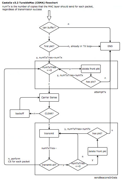
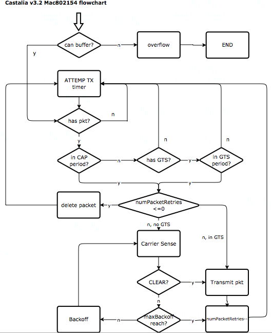
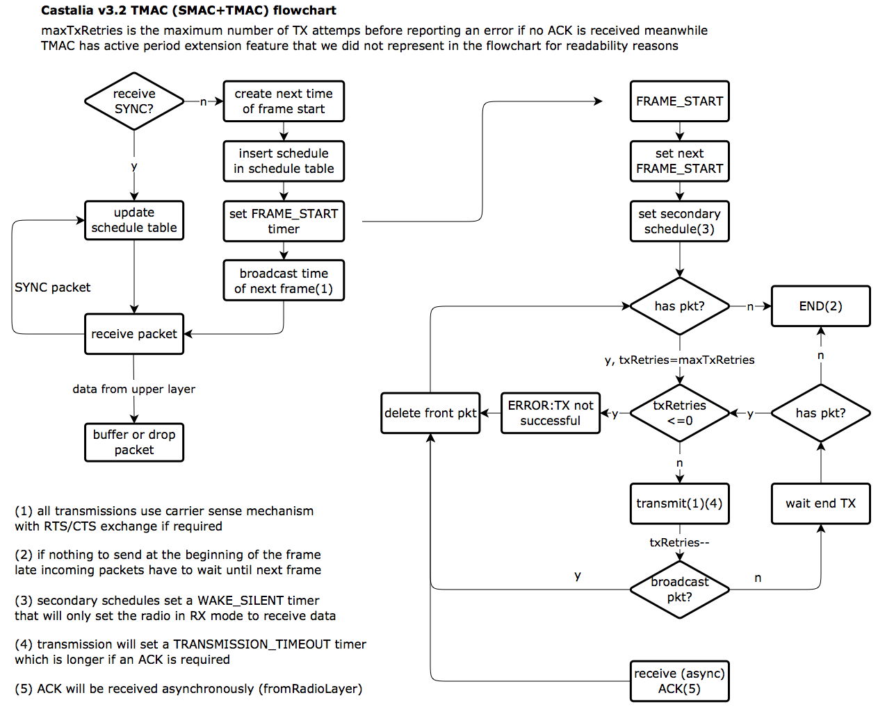
modeled when performing comparison studies. Here is a tentative
flowchart description of the classical CSMA, the 802.15.4 and the
TMAC/SMAC models as
implemented in Castalia v3.2.
These flowcharts are provided to help you understanding how these MAC
modules are implemented under Castalia, not how the corresponding IEEE
standards work. Although, the overall blocks can be quite similar, it
is better to know the corresponding MAC standards in order to fully get
the significance of these flowcharts. In addition, these flowcharts are
my personal view of how the MAC layers are implemented in Castalia.
There may be different ways to describe it this but I hope that these
flowcharts will help you understanding the Castalia implementation.
Also, it is better if you can have a look at the source code at the
same time: initially, the motivation of these flowcharts was to help
understanding the source code.
The classical CSMA model (and source code which is TunableMac.cc)
is quite easy to understand. I've not included the various
optimizations that are available such as p-persistance and backoff
types. Adding the duty-cycling feature will simply put in SLEEP mode
the radio when there is nothing to transmit so the impact on the MAC
layer description is very small. This is why I also chose to not
mention the duty-cycling feature in the flowchart. Note that Castalia
user manual indicates that TunableMac
module models an CSMA/CA behavior. However, as the RTS/CTS mechanism is
not modeled, you should be aware that the current TunableMac
module models a simple CSMA behavior, and not a fully CSMA/CA behavior.
It is not that important as RTS/CTS are considered quite costly for WSN
and CSMA will most likely be used, which justifies the Castalia model.
The Mac802154
module source code is a bit tricky. My flowchart interpretation is
certainly not the unique way, and it does not follow strictly the
source code, which is quite impossible to do with a flowchart, and not
the point anyway. However, I think that the main steps are here and
will help you understanding what is implemented compared to the complex
IEEE standard. Note that, as indicated in the Castalia user manual, the
non-beacon mode is not implemented. I did not put the flowchart for the
PAN creation by the coordinator, nor the synchronization phase of the
non-coordinator nodes before being able to transmit data. The flowchart
assumes that all these steps have been performed. These parts of the
source code are quite easy to understand so you just have to take a
look to the Mac802154.cc
file.
The TMAC module implements both TMAC and SMAC. Again, there are some
steps that are not represented in the flowchart: active period
extension, RTS/CTS exchanges and secondary schedule activation.
However, these omitted features can easily be identified in the source
code.
Last information: these
flowcharts have been created with the online flowchart tool www.diagram.ly. The .xml source files are
available here: TunableMac-CSMA.xml,
Mac802154.xml and TMAC-SMAC.xml.
Hope you find these information useful.
C. Pham.