Getting started with the XBee 802.15.4 (serie 1) communication
module
Introduction
There are many useful information on the web on this 802.15.4
communication from Digi.
This link
being one of them, this one
another nice one. It is one of the most popular communication module
for low-power devices and is considered as the de facto module for
many Arduino board with the wireless
shield (see here a link
on Lextronics for a more recent shield). It is also used in Libelium
WaspMote
sensor board and many other boards. You can find at the end of this
document more links on XBee.
However, I wrote this small tutoial page for students to get started
with the XBee module and be able to perfom the basic configuration
steps required before being able to build a comple communication
project. I hope you will find these information useful.
The XBee 802.15.4 offers the IEEE 802.15.4 connectivity in the
2.4GHz ISM band. There is a "pro" version where the output power is
higher, 63mW instead of 1mW, allowing for larger communication
range. The "normal" version is denoted XB24 where the pro version is
denoted XBP24. Also, the 802.15.4 version is referred to as "serie
1" while the ZigBee version, that needs a dedicated firmware and the
ZigBee higher layers, is referred to as "serie 2". This document is
for the serie 1.
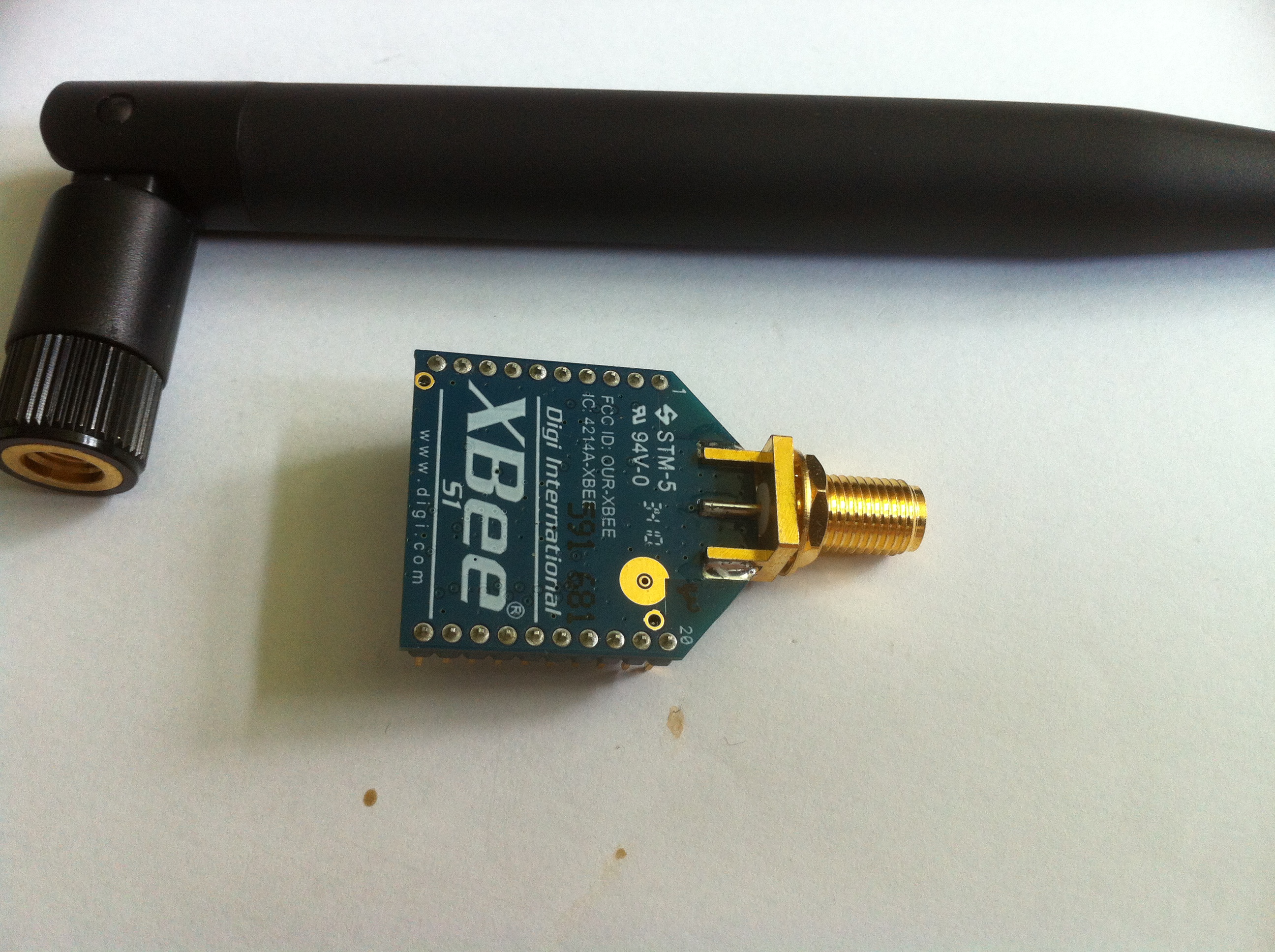
Practically the XBee module can be viewed as a modem because it
mainly uses a UART (serial interface) to communicate with the main
board. The advantage is simplicity and the possibility to re-use
many serial tool. One of the disavantage being perfomance in terms
of throughput given the fact that the serial link is the botteneck
of the system.
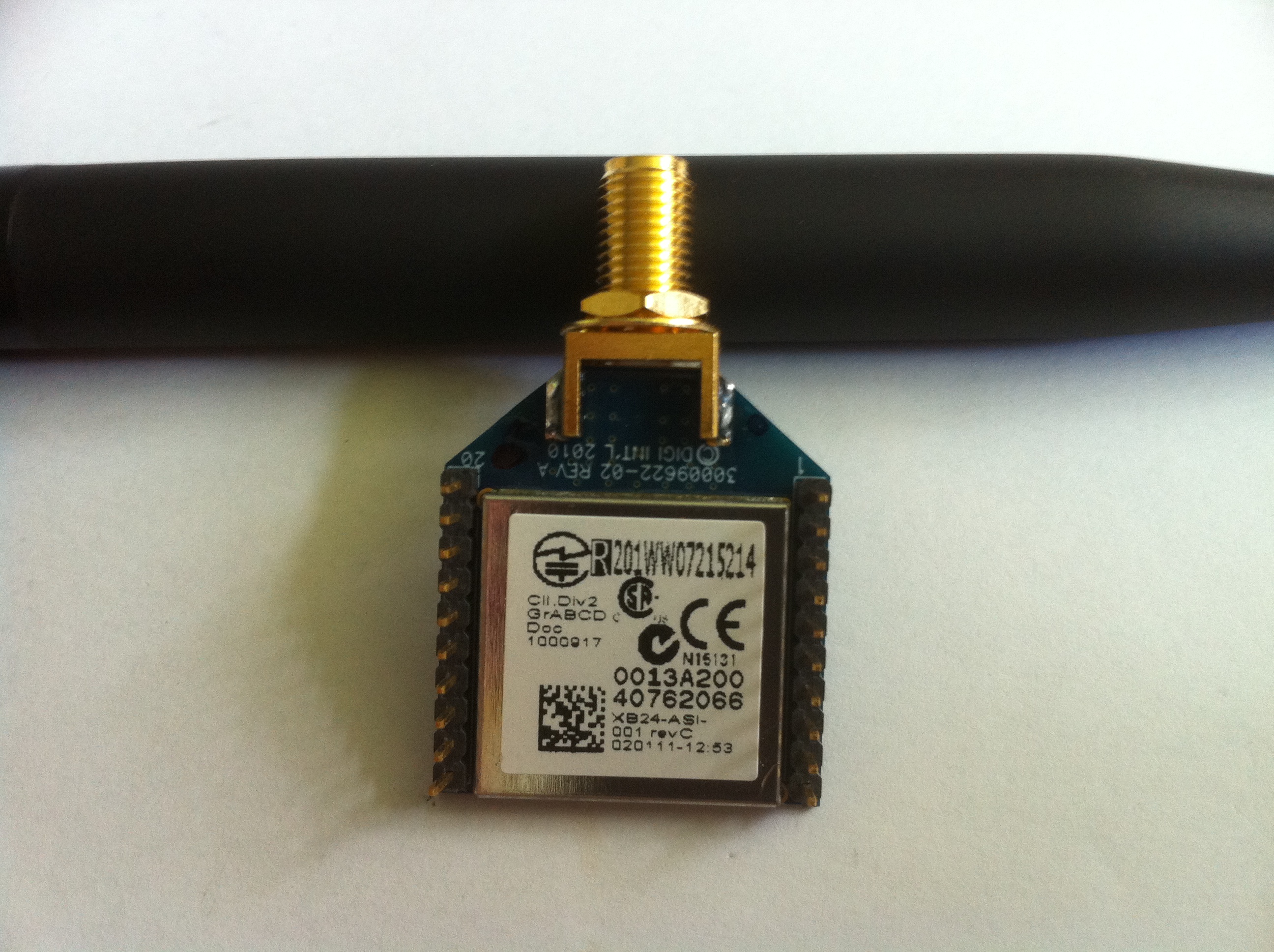
Each XBee module has its own MAC address which is a 64-bit address.
On the figure above, right part, you can see the MAC address:
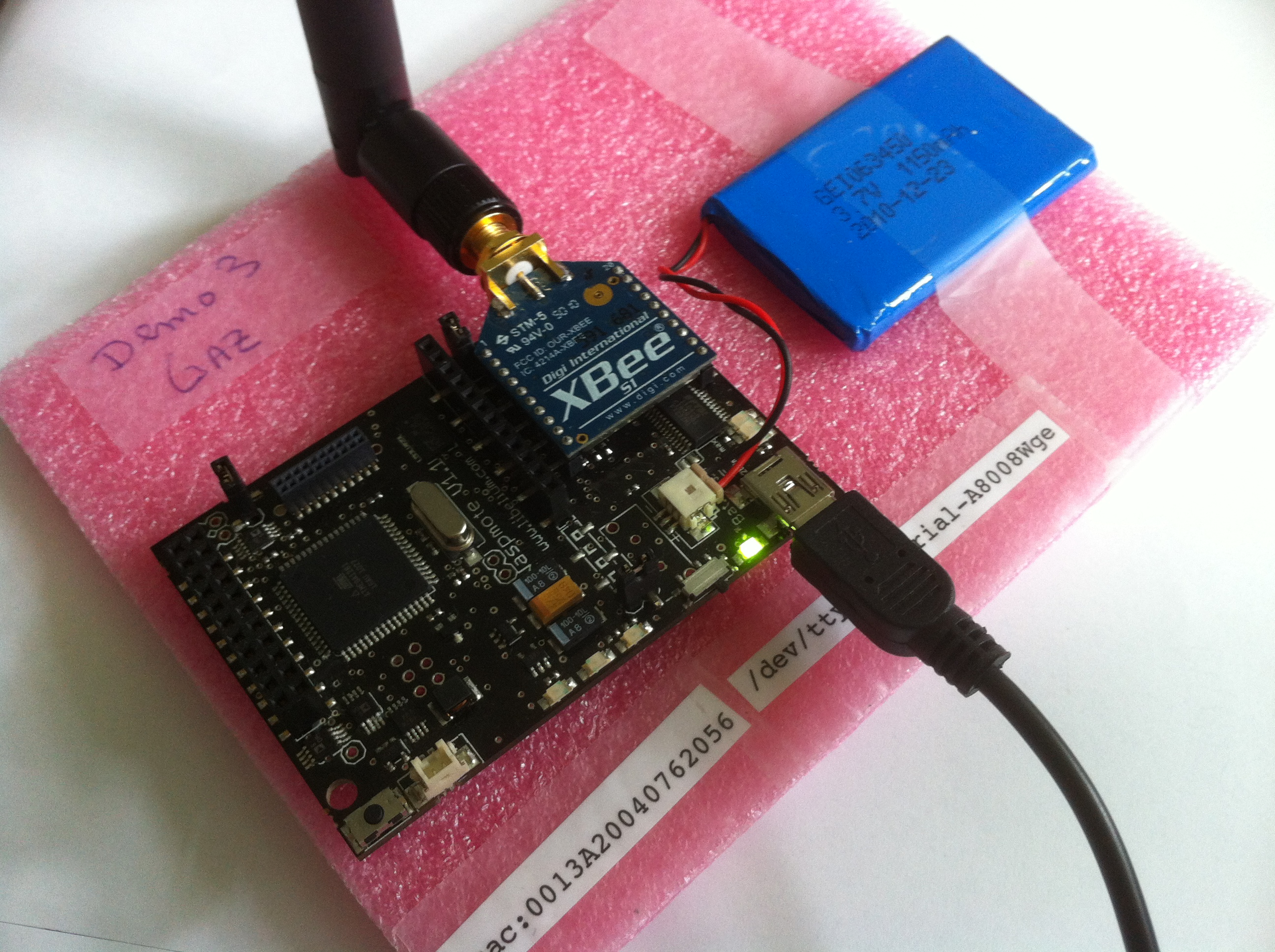
0013A20040762066. The XBee module can be plugged on a sensor board
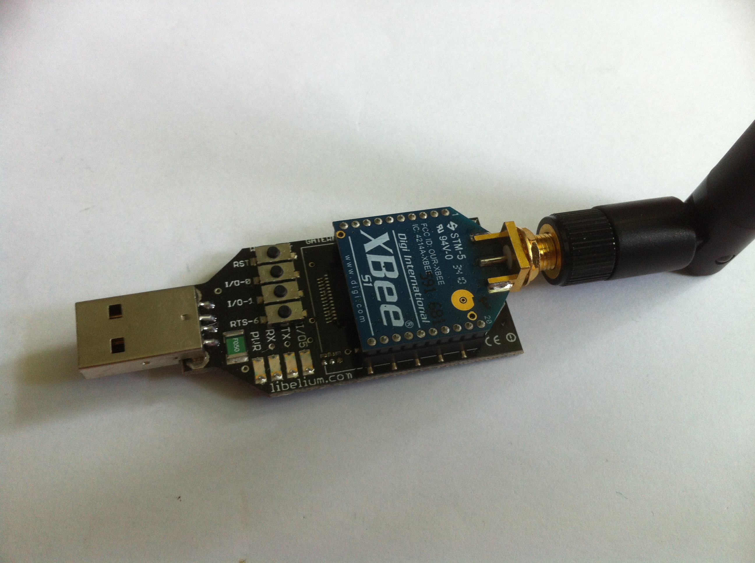
as the communication module, see figure below left part (such as a
WaspMote), or can also be plugged into a USB-serial converter to
serve as a gateway for your computer (PC, MAC, Linux,...), see right
part of the figure below.
Communicating with the XBee and basic configuration
This section is quite important and actually was the main motivation
for me to write this page. The fact is that if you want to make your
sensor nodes communicating and exchanging messages, you definitely
need to know the XBee configuration to be sure that the
communication module is capable to send and receive frames, and that
they have the same configuration to be able to understand each
other.
There are several ways to configure the XBee module. Digi proposes
the Windows-based
X-CTU tool for XBee configuration which works quite fine.
There are nice tutorials on X-CTU on the web. If you need to upgrade
the XBee's firmware, X-CTU is the tool. One other advantage of X-CTU
is that you can have a quick summary of all the XBee's parameters.
However, if you need fast configuration or just to check some
important parameters, a more flexible and simple solution is to use
the USB-serial interface to access to the XBee module with a serial
tool such as "minicom" on Unix-based machines or "Zterm" on MAC
computers or "HyperTerminal" on Windows-based systems. It is also
much more funny!
As the XBee communicates through a UART, you have to set the right
baud rate, parity mode, ... The default factory settings for serial
communication with the Xbee are:
- baud rate : 9600
- flow control: none
- data bit: 8
- parity: none
- stop bits: 1
If you don't know the baud rate, you have to try several values.
I've heard that there are tools that could check and try several
baud rates in order to automatically find the adequate baud rate. It
is most likely that your XBee module comes with some different
settings, especially for the baud rate. For instance, my
Libelium-shipped XBee has a settings of 38400.
Once you are connected to the XBee with the serial tool, the
configuration process can begin. Actually, even if you do not want
to configure the XBee, it is very useful to know the current
configuration in order to decide whether it is your code or the XBee
configuration that should be incriminated. For instance, if you
cannot receive message that you are sending from one XBee to another
there could be many reasons: either your protocol is badly
implemented or the XBee have mismatched configuration that make them
unable to communicate. Mismatched configurations can also have a lot
of reasons (MAC layer can have many operational parameters for
instance) because there are lots of parameters that can be set on
the XBee. Here are the most common problems:
- the 2 XBee are not in the same network
- one XBee is using encryption while the other does'nt
- both are using encryption but the encryption key is different
One solution is to restore both XBee to factory settings and set the
relevant parameters you want to change to identical values. Since
the XBee can be viewed as a modem, it can be configured with AT
command. The list of AT command supported by the Digi XBee can be
found in the product manual. For the XB24 and XBP24 802.15.4 a copy
of the August 2012 manual can be found here.
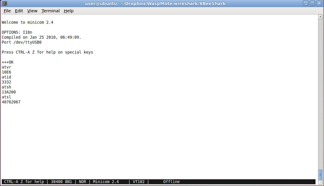
Using minicom for connect to the XBee you can then use AT command to
read and set parameters.
First of all, the XBee modem need to be in command mode in order to
accept input command. This is usually performed by sending "+++" and
waiting for the "OK". You
need to make sure that your serial tool will send each character as
soon as you type it and does not wait for a return. The default
configuration of minicom works. However, you have to set local echo
on in order to see what you are typing. Once again, it may depend on
the tool that you ae using. In case of minicom, the local echo on is
not the default mode and it has to be set appropriately (CTRL-A Z
then E). Note that the modem has a
default time for staying in command mode. After that amount of
time, you have to repeat the "+++" sequence.
Once you got the "OK", you can start typing AT command such ATVR
which shows the firmware version, here 10E6. Then ATID shows the
network ID. This is probably the most important parameter since 2
XBee in different network id won't be able to communicate! My
Libelium WaspMote comes with an XBee configured on the network id
1234 (in hexa). The factory setting from Digi is 3332. There is also
the radio channel (not shown in the figure above): ATCH gives C for
the Digi factory settings and D for my Libelium XBee.
In the figure above, the 2 command ATSH and ATSL shows the serial
number high (32 bits) and serial number low (32 bits) that form the
64-bit MAC address. Here the MAC address is 0013A20040762067. Note
that the first 2 zero of the high part are not shown but they are
necessary for correct addressing!
The Digi XBee also comes with other important factory settings such
as:
- AES encryption enable: default is 0, ATEE gives 0
- API enable: default is 0, ATAP gives 0
Encryption setting was one of my source of problem: My Libelium XBee
comes with ATEE=1 but the encryption key cannot be read (obviously
for security reasons) so so can either set a new encryption key for
both XBee with ATKY or disable encryption with ATEE0 which is
probably better for lab training.
Making 2 XBee compatible
To summarize, if you want to make sure that 2 XBee are able to talk
each other in order to debug you protocol code, you can restore
factory settings and if necessary reconfigure the important
parameters. An example is given below, to be performed on all XBee
that need to be "reset".
+++OK
ATRE (don't do the reset if you are not sure
to reset the XBee!)
OK
ATID3332
OK
ATCHC
OK
ATBD5
OK
ATWR
OK
The last command writes the configuration so that it becomes the new
configuration saved in the modem's memory. These commands give you 2
XBee on network id 1234 and channel D, with no encryption and
working at 38400 bauds. NOTE:
after the ATRE, the baud rate is set to 9600. If you were
connected at a different rate, you have to set 9600 as the new
rate for your serial tool and connect again to perform the next
commands. After the ATBD5 command, you have to set again the baud
rate to 38400 to be able to communicate with the XBee!
API mode vs AT command mode
The XBee can operate in AT
command mode or API mode. In AT command mode, if you want to send a
packet, you have to issue a number of AT command to set the
destination address for instance. This mode is not flexible. The
XBee module from Digi can operate in API mode (atap1 or atap2) in
which case it can accept structured frame containing all the
required information (such as the destination address) needed for
sending the packet. Note that it has nothing to do with the fact
that the XBee can be accessed with a serial tool such as minicom and
programmed online with AT commands. Even if you use the API mode,
you can always have access to the XBee module with minicom for
instance. This is only for sending packets from a program. By
default, the Digi XBee is in AT command mode (also called
transparent mode) while the one shipped by Libelium is in API mode 2
(atap2) where some characters are escaped using the escape character
0x7D. The Libelium API assumes that the XBee module is in API mode 2
anyway. Here is what you can read in page 56 of the Digi Xbee
product manual:
Escape
characters. When sending or receiving a UART data frame, specific
data values must be escaped (flagged) so they do not interfere
with the UART or UART data frame operation. To escape an
interfering data byte, insert 0x7D and follow it with the byte to
be escaped XOR’d with 0x20.
XBee with Digimesh firmware
The XBee module serie 1 can be upgraded to have the DigiMesh
firmware (in the case you didn't buy the version with the DigiMesh
firmware of course) which adds a proprietary on-demand (like AODV)
routing protocol. There is a note
from Digi regarding this compatibility issue: normally, recent XBee
modules shoud be able to have the DigiMesh firmware. There is a nice
tutorial here from Libelium that shows you how to flash an
XBee 802.15.4 serie 1 with the DigiMesh firmware.
It is not very clear how XBee 802.15.4 and XBee DigiMesh 2.4 can be
compatible and communicate together. The preliminary tests were not
very successfull: it seems that the radio firmware is doing some
filtering. More tests are needed.
Some additional links
Now that you can configure your XBee module, nothing prevent you
from making your sensor board communicating. It's now time to
program the sensor and this is an other story. If you have Arduino
board, check the Arduino web site. If you have WaspMote from
Libelium, there are a lot of code example
on Libelium web site. You should also check their 802.15.4
programming
manual which contains lots of useful information.